Week 7: Electronic Output devices
Overview
1: Use an output device that you haven't used before.
I'll be using a Servo :)
2: Write a microcontroller program that integrates at least one input device and one output device. Avoid the delay() function by using either timers or interrupts.
For this week, I really wanted to make a useless machine. Here (opens in a new tab) is an example of a useless machine.
Essentially, you press a toggle switch and a mechanical hand pushes it back. I love the humor and the irony behind it and have always wanted to build it.
I end up trying a button/LED thing instead.
3: Use an oscilloscope to discover the time domain at which your output device is operating. Is it on a fixed clock? What's its speed? Share images and describe your findings.
I talked to Nathan about this. I realized retroactively I didn't do this and since I had COVID, he said it was fine that I didn't do this.
4: Prepare CAD files for CNC week (after spring break). Consider either 2D DXF files for routing sheet material (like plywood or OSB), or 3D STL files to mill out a (2.5D) shape. We will also cover molding & casting, so you may want to consider milling a mold. Done! I detail my CAD files/what I did in the Week 8 tab :)
Building the Useless machine
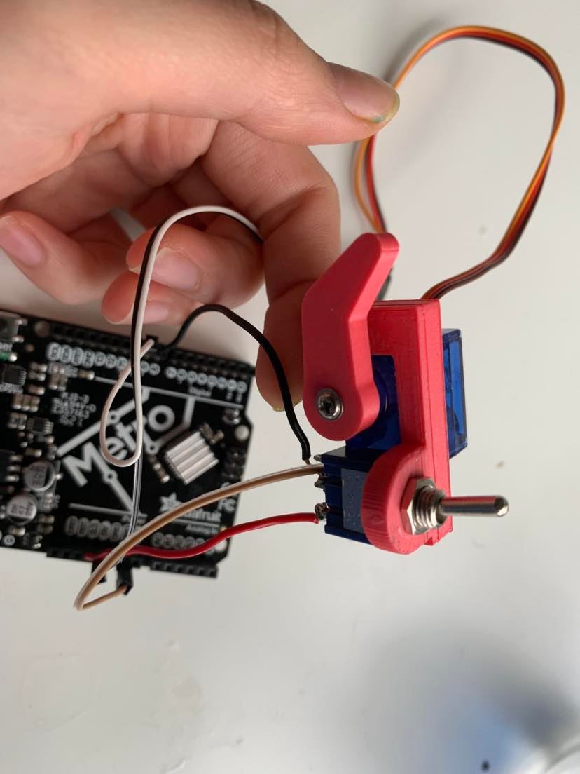
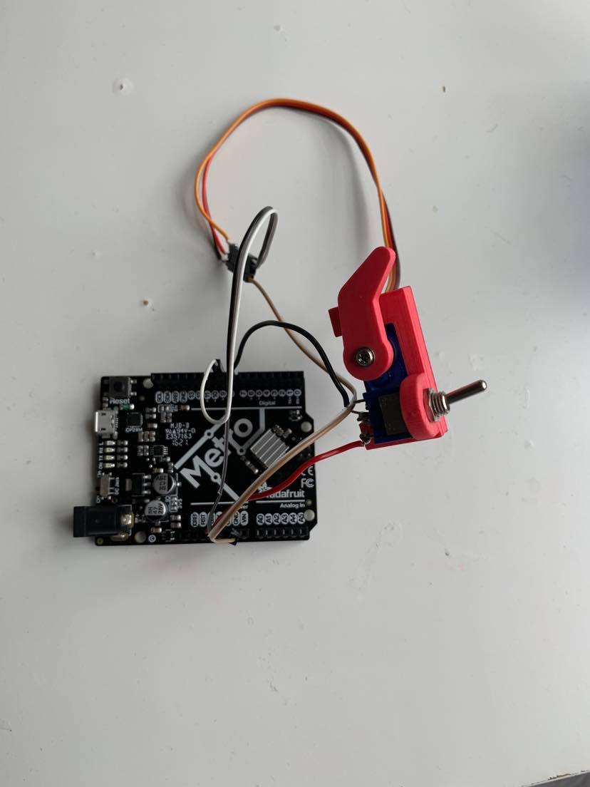
I decided to follow the instructions on this website to make the useless machine. https://www.thingiverse.com/thing:4561617 (opens in a new tab) On the website, the STL files are provided. I was able to downloaded the STL files and put it directly into the slicer. After I printed out the pieces, I was able to assemble it onto my Servo with a flat head and a pan head screw.
I then plugged it into my arduino.
This is what it looked like after I assembled the different pieces together.
Code
I first used this simple Servo code to try to see where the position of the pink arm would be at 0, 90, and 180 degrees. That way, I could figure out/calibrate what the degree is in which the pink arm could push the lever. Through testing, I found out that the off position is 7. Home is 100 degrees.
#include <Servo.h>

Servo myservo;  // create servo object to control a servo

void setup() {
  myservo.attach(9);  // attaches the servo on pin 9 to the servo object
}

void loop() {
  myservo.write(0); // tested with 0 degrees, 90 degrees, 180 degrees
}
</code></pre>

I then was able to make this code

<pre><code>
#include <Servo.h>

Servo Myservo;
int switch_pin = 8;
int servo_pin = 9;


void setup() {
  pinMode(switch_pin, INPUT);
  Myservo.attach(servo_pin);
  }

void loop() {
  if(digitalRead(switch_pin) == HIGH){
    delay(1000);
    Myservo.write(7);
    delay(900);
    Myservo.write(100);

  }
   if(digitalRead(switch_pin) == LOW){
    delay(10);
    Myservo.write(100);
  }

}
Here is the corresponding footage.
As you can see, when I push the toggle switch, the mechanical hand pushes it back, making it work: yay!!
I then continued to try to get rid of the delay function by writing code with the interrupt function.
This took FOREVER with lots of debugging. To debug, I put a bunch of print statements. I tried many variations of the following code with no luck
// variables will change:
volatile int buttonState = 0;         // variable for reading the pushbutton status

#include <Servo.h>

Servo Myservo;
int switch_pin = A2;
int servo_pin = 9;
boolean switchState = LOW;

void setup() {
  Serial.begin(9600);
  pinMode(switch_pin, INPUT);
  Myservo.attach(servo_pin);
  attachInterrupt(switch_pin, pin_ISR, HIGH);

}

void loop() {

 // if (analogRead(switch_pin > 500)) {
 // switchState = HIGH;
// }
 // else {
  //  switchState = LOW;
  // }
  Serial.println(analogRead(switch_pin));
}

void pin_ISR() {
  Myservo.write(7);
  delay(900);
  Myservo.write(100);
  Serial.print(1);
}
LED/Button
I tried to use the interrupt function so when I press a button, it turns on an LED. I followed tutorials that explained how to use the interrupt function, so as this one: https://www.youtube.com/watch?v=QtyOiTw0oQc&t=251s (opens in a new tab)
I then ran the code and it worked! Code referene: https://www.allaboutcircuits.com/technical-articles/using-interrupts-on-arduino/ (opens in a new tab)
I wired the breadboard as a simple circuit where the button is connected to the LED:
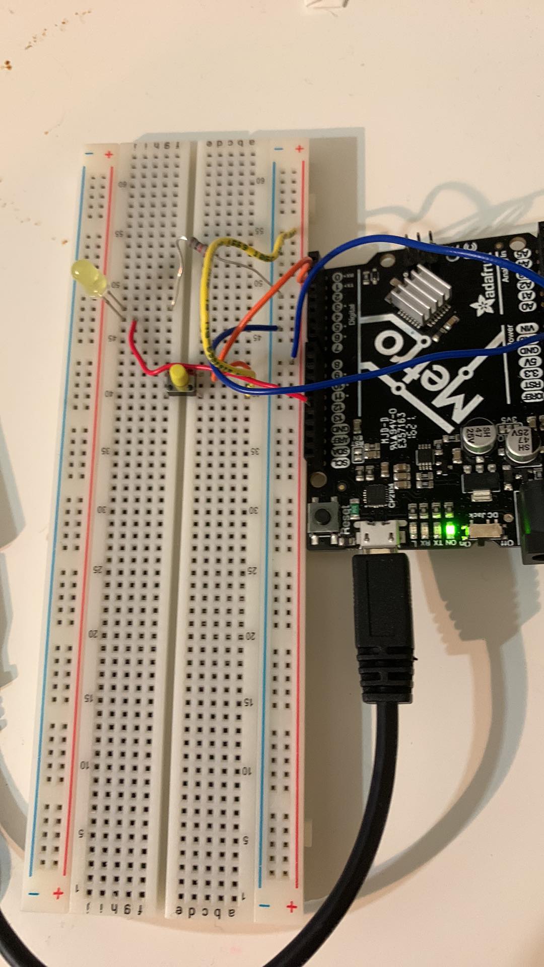
const int buttonPin = 2;     // the number of the pushbutton pin
const int ledPin =  13;      // the number of the LED pin

// variables will change:
volatile int buttonState = 0;         // variable for reading the pushbutton status

void setup() {
  // initialize the LED pin as an output:
  pinMode(ledPin, OUTPUT);
  // initialize the pushbutton pin as an input:
  pinMode(buttonPin, INPUT);
  // Attach an interrupt to the ISR vector
  attachInterrupt(0, pin_ISR, CHANGE);
}

void loop() {
  // Nothing here!
}

void pin_ISR() {
  buttonState = digitalRead(buttonPin);
  digitalWrite(ledPin, buttonState);
}
Here's a video of it working:
As noted, I wasn't able to use an oscilloscope and talked to Nathan about it and he said to not worry about it since I had COVID when I realized this part of the assignment!
Reflections
Honestly, working with the useless machine was a little frusturating because of the troubleshooting that came with it and with no fruitful result. Overall, though, it was good to learn how to use the interrupt function. Many YouTube tutorials I watched talked about how interrupt is an underutilized function, so I'm glad to have learned it.