Week 4: Microcontroller programming
Expanding upon last week's project: periodic table illustrating the chemistry career of Christina Woo :)
Background on Project
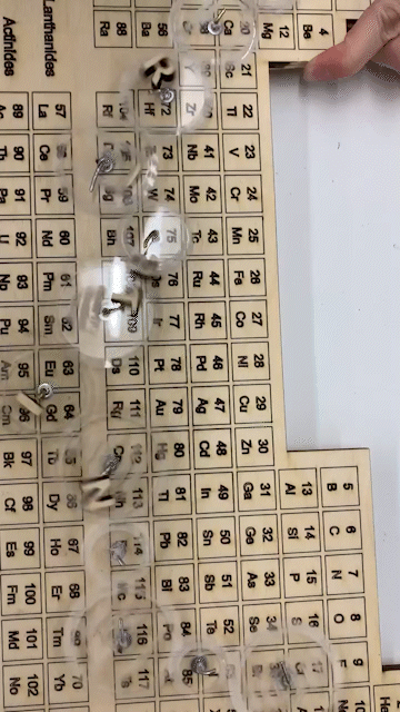
Last week, I made a wooden periodic table for Christina Woo with clear acryclic gears attached on top. These acrylic gears could be turned by hand or by motor, and each gear has an engraving coresponding to Christina's interest. I got inspired by using this project as a gift for her because "gears" are often thought as an analogy for thinking ("my gears are turning") and I thought the gears were also a good depiction of how chemical biology builds on top of itself and that with each turn and advancement in the field and with research interest, it influences others as well (hence the linking together of the gears). For more details about the build of the wooden periodic table with corresponding clear acrylic gears, look at last week's entry.
This week, I decided to expand upon this project by working specifically on the motor attached to one of the acrylic gears, which in turn turns the rest of the gears. As this is the first time I worked with arduino and C++, I wanted to learn a lot and thus decided to build a code that could control the gear with a button.
I took this week as an experimentation of:
- How to make the gear turn with the button press (but off otherwise).
- Switch the direction with the press of the button
- Speed up the gear with the press of the button. After all, I may not necessarily want my gear to turn with full speed at every second. Thus, I want it to be controllable with the button. All of my work is done with the gear attached to the motor. As demonstrated last week, the gear can turn the rest of the gears, and so I thought it would be more navigatable with working with the gears spearately.
I discuss how I made the code to do these actions and how I troubleshooted these. I also discuss my circuit design. I took a lot of time in trial and error so would be discussing them.
For reference, here is the gif of it turning with a motor from last week! It turned quickly :)
Updates to the periodic table with gears
I first made some modifications to the board. As mentioned last week, one of the biggest problems I had with the board was that the letters would either collide with each other with turning or interfere with the wire that turns in the middle of the gear.
Specifically, the O gave quite a bit of trouble since it's on a gear that is small. Hence, it would either bump with a neighboring letter or interfere with the wire that's in the middle of the gear.
Thus, I decided to rewire the gear attached to the O to have the wire to loop over the O rather than like the other gears where the letter is next to the wire.
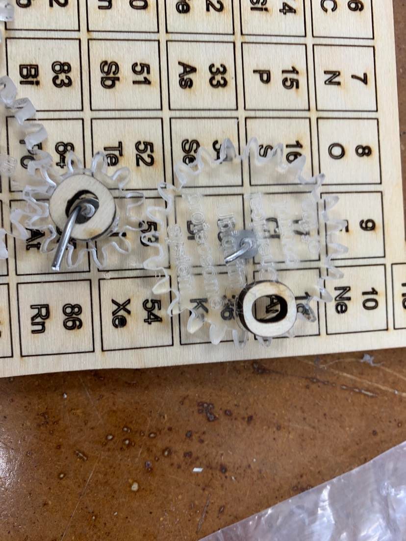
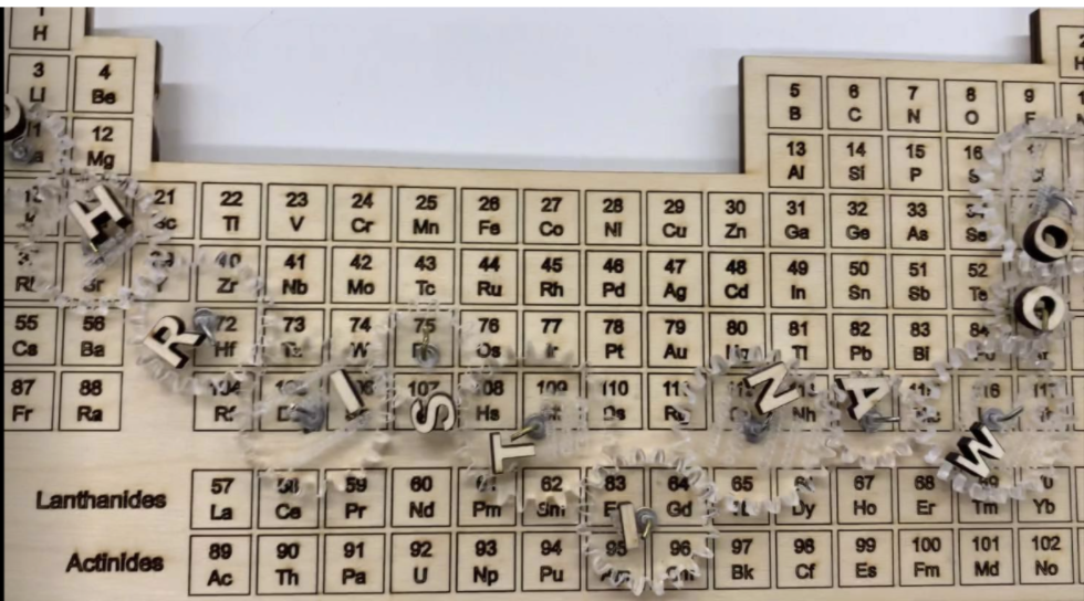
In addition, I reglued the letters to ensure they wouldn't collide by placing them side by side on the gear (worst case scenario) and ensuring they wouldn't collide into each other when that happens. Moreover, I reprinted the W to be slightly smaller in order to not block any of the engraving on the acrylic gears. Here it is displayed with the letters spaced in the optimal distance apart.
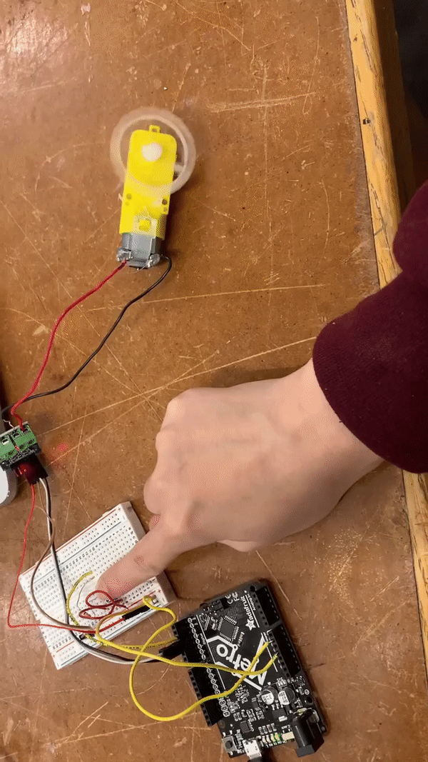
Circuitry
For lab, I had done the exercise that made the LED light turn on with the press of the button. I also separately made the circuit and ran the corresponding code to make the motor pause for a certain amount of time and turn for a certain amount of time. (reference here: https://nathanmelenbrink.github.io/ps70/04_arduino/arduino.html (opens in a new tab)). These were the inspirations I had for my objective to have my motor turn controllable by the button. Here is an example of the circuit I had in class where when I pressed a button, the LED would turn off.
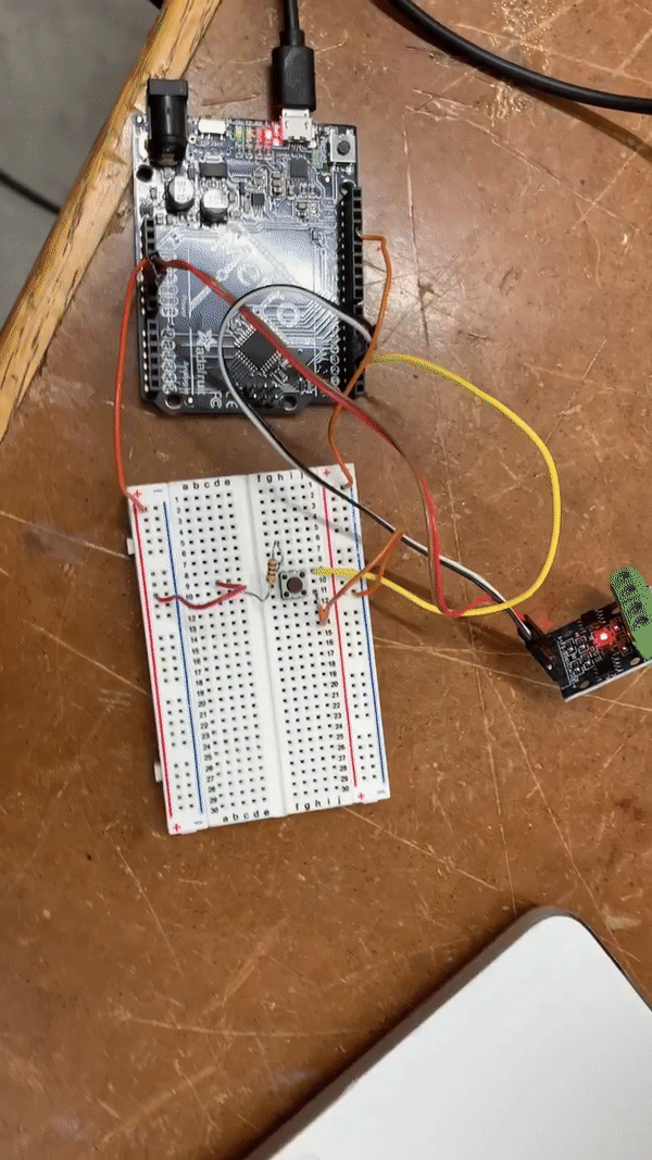
This circuit went through many renditions. But ultimately, I decided to go with the following circuit.
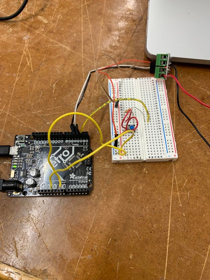
Notably, the digital output that connects to the L9110 is the black and white wire in pin 3 and 4. This is important because I would have to later indicate this in my code as the output. Moreover, I have a 4-pronged push button (I originally used a 2 pronged push button, but that was harder to use and for me to visualize when I had so many wires). Moreover, my button is controlled by pin 3.
In addition, I subbed my resistor out for a stronger resistor (30k Ohms, 5%) because I was concerned that my leaky voltage (will be described in the next section) was attributed to too weak of a resistor. I have my breadboard connected to 5V through a yellow wire. Essentialy, with the design of my circuit, no voltage would go through unless I press the button, which would then allow the flow of electricity between the two pink wires and hence from the arduino to L9110 the motor.
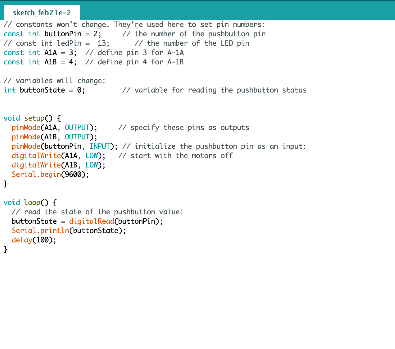
Code
I first wanted to make my button control having the motor turn. With the press of the button, the motor should turn. To do this, I looked at some example codes and learned the structure of the arduino code. Essentially, I first set the constants by designating which ones corresponded to my motor output and my button input.
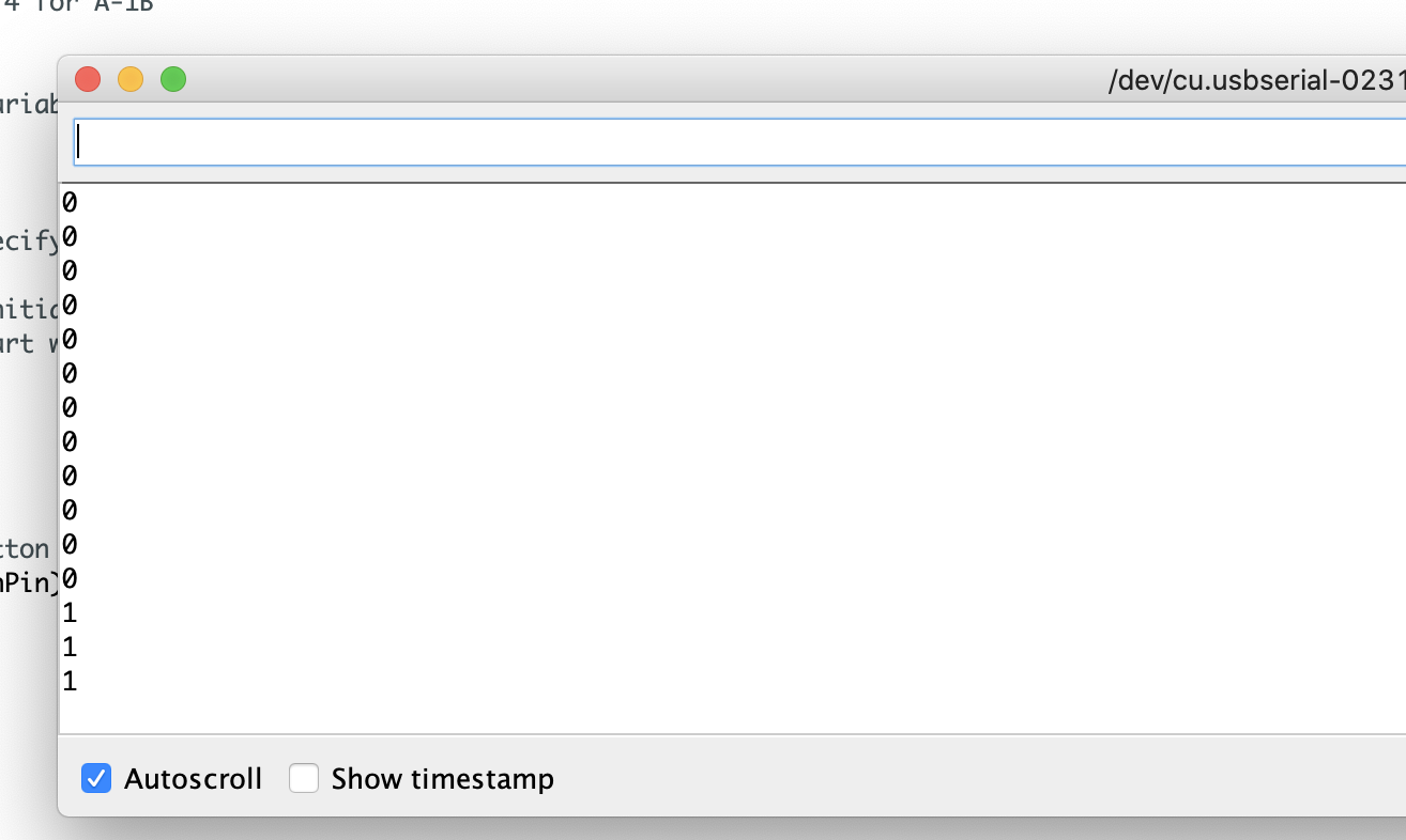
I first tested to make sure my button worked. To do this, I made this code that would give me an output of zero when not pressed and 1 when pressed, theoretically.
At first, I got a bunch of sporadic/inconsistent 0s and 1s, which is why I swapped my resistor to one that had a higher Ohm value than before (30k Ohms, 5%). After this modification and additional tinkering to ensure all my wires were secure, I got the following display of 0s when the button is not pressed and 1s when the button is pressed, which is what I needed.
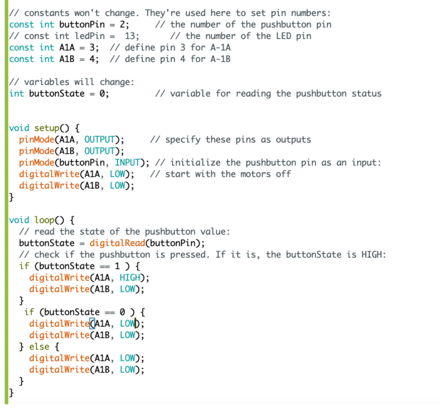
Originally, I made the following code to make my motor turn only when the button was pressed.
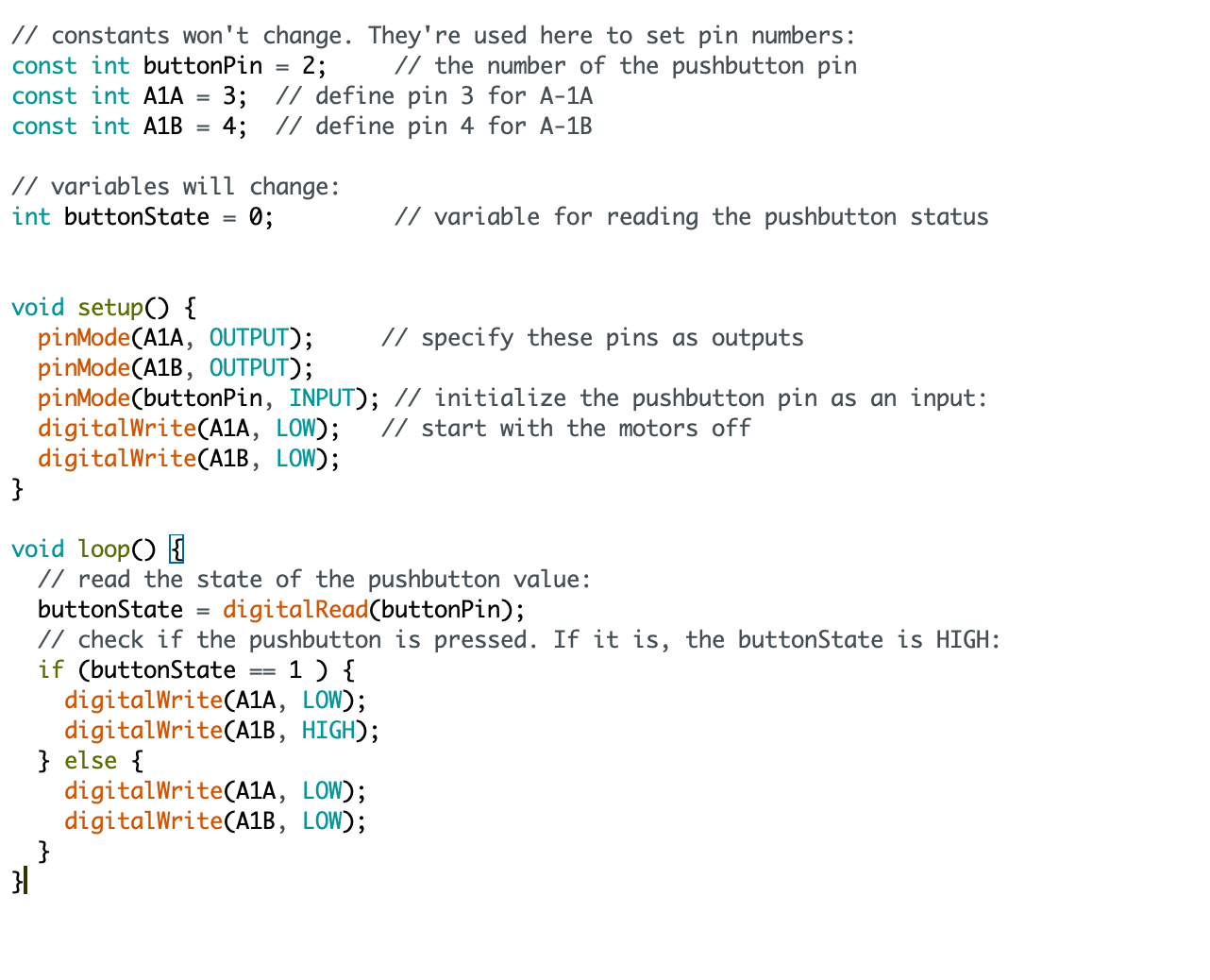
The thought was that without a button press, the motor would not operate (hence the double LOW in the else statement). With the button press, it would result it in turning (Hence the HIGH, LOW). A huge problem though, was that when my arduino complex was plugged into my computer, there was turning even when the button wasn't pressed. However, with a button press, it would turn quicker. In addition, I found that if I made the else statement had both of the outputs as HIGH HIGH rather than LOW LOW, there would be an initial higher speed that when, with the press of the button, would make it go even faster.
I tried to debug this--I think there's leaky voltage. However, my circuit made
sense and my button worked as indicated by the 0s and 1s. I even asked my
friends and both the circuit and code made sense to them, and there was no luck.
I also tried putting an additional if statement that corresponded to if
buttonState == 0 just in case it had do with a problem with the else
statement. However, this yielded no luck.
Hence, I decided that since one of my objectives was to have a situation where the button would make the motor turn quicker, I did in fact experimentally achieve this result.
Here is the video of it turning quicker with the button press. I decided to make this a video instead of a GIF so you can also press the difference in motor sound upon the press of the button (aka you can see the change in speed as demonstrated both visually and audibly). Here it is. (opens in a new tab)
This was with the turning of it with the else statement having both of the outputs as LOW. When I made both of the outputs for the else statement as HIGH, the intial speed was higher and it increased with the press of the button. This would be a cool setting/feature/knowledge for future projects.
In addition, while playing around, I realized that I could make the motor turn
the other way with a button press. I found this out when I was curious what
would happen if alongside, my buttonState == 1, I inserted a
buttonState == 0 and else statement with conflicting code (aka A1A = LOW and
A1B = LOW for one, and A1A = HIGH and A1B = HIGH for the the other). Apparently,
when I do that (here's my code):
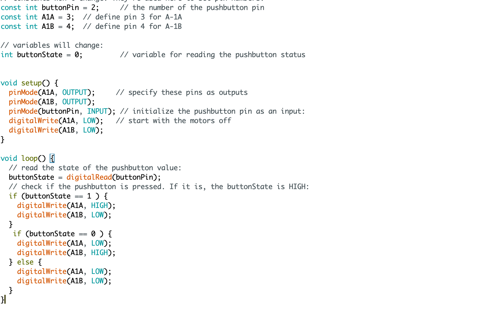
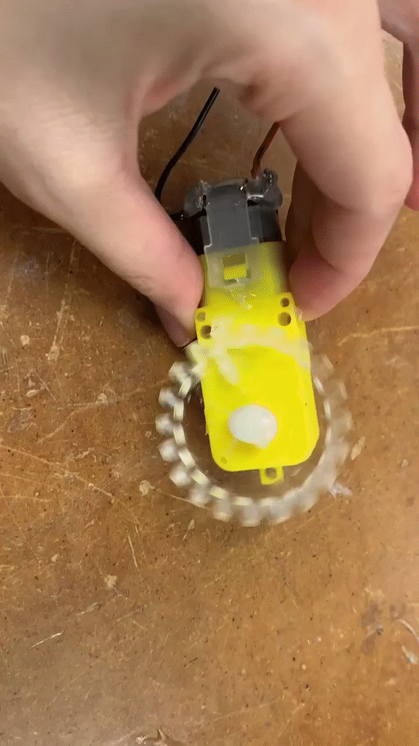
I get the motor spinning in one direction but it spins in the other direction when I press the button. Here is the corresponding gif.
Admittedly, I don't really know why that happens (this is my first time coding this and my CS knowledge is zero), but again, I am evoking my spirit of an experimental scientist and just taking note that this is what happens with that code.
To make a way for the button to be default off but turn on with the putton press, I made the default position (without button press) to tell the motor to go in the other direction as the way it usually turns. This is because I had the "leaky" voltage that caused the motor to turn clockwise even when the button is not pressed. Thus, by turning the motor counterclockwise when the button is not pressed, the counterclockwise turn counters the clockwise turn and causes the motor to stop. This is the corresponding code.
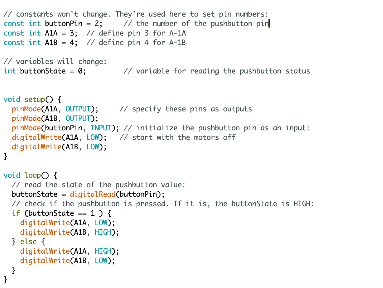
This actually worked! Here's a gif demonstrating the success.
Final reflections
This was my first time using an arduino, and I also had no prior electronics experience. It is great to know and be able to figure out how to troubleshoot, how to make a circuit, how to write code, and how to program an arduino. I also learned a lot about adapting and using trial and error (as an experimental scientist, I approve) to get the desired outcome. I am very proud that I was create a circuit and code (which are two skills I previously did not have) to get my motor to 1. make the gear turn with the button press (but off otherwise). 2. Switch the direction with the press of the button 3. Speed up the gear with the press of the button.