Week 3: Mechanical Design
Moving through the chemistry career of Christina Woo
Background on Project
I am making a gift for Christina Woo, a faculty of Chemistry and Chemical Biology here at Harvard. She was my professor of Chem 17 (Principles of Organic Chemistry) and Chem 170 (Chemical Biology) and has been an amazing mentor.
Thinking about Christina, I decided to make a wooden engraved periodic table as the background board. In the front, I would have clear acrylic gears that are engraved with key highlights of her research, such as DISCOVERY OF SMALL MOLECULE BINDING SITE HOTSPOTS, CHEMICAL CONTROL OF THE O-GLCNAC PROTEOME, and CHEMICAL CONTROL OF THE UBIQUITIN PROTEASOME SYSTEM. In addition, I would have gears corresponding to the three courses she teaches(mass spectrometry nanocourse, Chem 170, Chem 17) In total, I had 12 gears. These gears would be movable by a motor for the purpose of this assignment, but notably, should be removable since I am not giving her the arduino Thus, this design should also be hand-operatable. These were the constraints I was working under.
I got inspired by using this project as a gift for her because "gears" are often thought as an analogy for thinking ("my gears are turning") and I thought the gears were also a good depiction of how chemical biology builds on top of itself and that with each turn and advancement in the field and with research interest, it influences others as well (hence the linking together of the gears).
I started by drafting and drawing on paper and chalkboard.
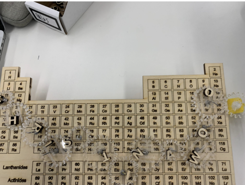
This is the final piece. It is a periodic table with a name on it. In this section, I will be discussing the troubles I had along the way and also the successes.
Here is the gif of it turning with a motor! It turned quickly :) I liked the fast speed (this gif is real-time), although I could adjust it with the potentiometer.
Designing and cutting the gears
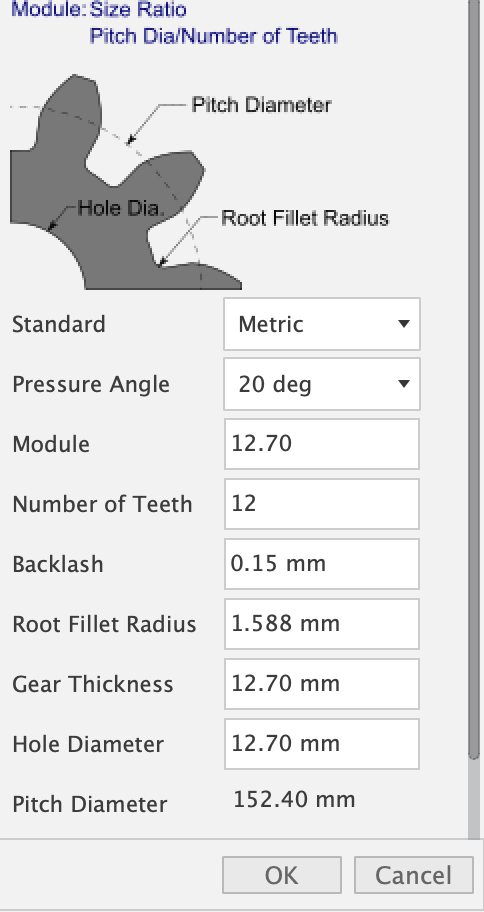
I used the Fusion plug in. In total, I needed 12 gears. I made two of them 14 spoke, two of them 16 spoke, two of them 18 spoke, two of them 20 spoke, two of them 22 spoke, and two of them 24 spoke. I used the settings displayed in this screenshot and just altered number of teeth.
I then typed 3 research interests of Christina Woo into three of the gears. Since her research topics have pretty long names, I just engraved on the ones with 22 spoke and 24 spoke primarily. I then typed the names of the 3 courses Christina teaches into three of the spokes.
I also had a spoke that had a bigger hole (6X6) for the motor to attach to.
On the laser cutting software, I then sized it down and saved the file so I would have the dimensions at hand in case I would ever need to reprint (which happened quite often) This was a very very long process in terms of laser cutting. I never worked with acrylic before and the settings were very nit-picky. Since I was engraving words on top of the gears (which were small), a lot of time cracking would occur. For instance, compare the difference between these two images, which had two different settings. Thus, it took me a while to adjust the settings in order to get legible engraving. I had six tries of adjusting the power before I got the right depth of cut. Ultimately, the settings that worked for me were Spd: 5 Pwr: 70 for the portion I wanted to cut out and spd: 85 pwr: 1 for the part that I wanted to etch.
Designing and cutting the periodic table
I found a black and white periodic table that I liked online. Unfortunately, it was not an SVG file and it became blurrly when I converted it to a SVG file. I had to find multiple black and white periodic tables until I found one I decently liked. I then went to illustrator and cleaned it up by deleting unncessary text. Im addition, I used the pen tool to trace around my periodic table to ensure a laser path could cut through it.
I used the laser cut to etch and cut. The etching was done with a speed of 10 and a power of 10. For the outline which I need to cut, I used a sped of 30 and a pwr of 75.
There were some parts of edges that the laser cutter didn't go through though, so I recruited Suvin to help me use the scroll saw to cut some parts of it.
Designing the Name
I then wanted to attach her name (Christina Woo) on top in some form. I initially attempted wire bending; since I designed my gears to attach to the periodic table through wire, I thought I would have the wires that stick through the wood to be longer so I could bend it into the letter of names. I got through making 3 letters and ran out of wire and decided it wasn't feasible. The thinner wire that was available wouldn't hold its shape and the thicker wire was too thick to bend.
Hence, I decided to laser cut the letters. At first, my letters were too skinny and those fell through the grates of the laser cut machine. Then they were too big and couldn't fit on all of my gears without blocking the engraving. Ultimately, what worked was Arial Bold font to make it thicker so I could scale it down.
Assembling
Overall, what I did is I used the drill press to make holes corresponding to the center of gears. I then put a washer between my gear and the board to reduce friction. The gears and washers were attached to the board with wire that I had bent. I then put the letters "Christina Woo" onto the clear acryllic gears. I then attached my motor. Here is a picture of a closeup of one of my gear complexes.
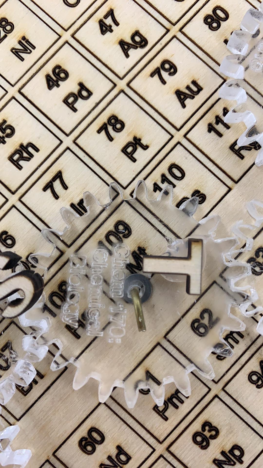
Notably, to make sure my gears could turn each other, I drilled and attached them to the board one at a time. Aka I would drill a hole and attach everything before
I basically assembled everything first before gluing my letters on. There was a lot of trial and error involved primarily because if the wire got bent in the part that touches the gear or the washer, the gear won't turn smoothly. Hence, I had to reattach the gear many times, as well as experiment with different gears to make everything flow smoothly. I basically used my hands to manually turn these gears while I was trying to figure out how to make the spacings work.
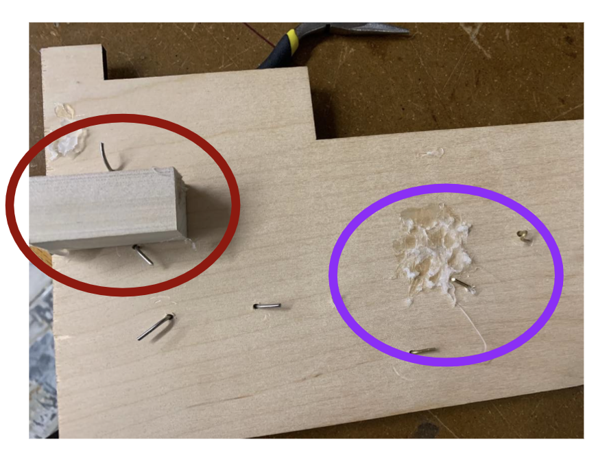
I got it to work extremely well, and my motor was attached to the side. In addition, I had a block of wood I used to attach to the back to prop up the periodic table and a block as a shelf for my motor. The red circle is the shelf for the motor at the box. The purple circle is the hotglue that held up the wood that holds up the periodic table when it's on display.
GOOD NEWS: After assembling everything worked and everything looked nice. I also attached my motor on the shelf on the back of the periodic table, and with glue with extra stability, and my motor turned everything well. I also made sure that the distance between the motor and the gear was the same depth as the thickness as the plywood to have the gear perfectly sandwich and rest on top of the periodic table. I was also super proud of it considering all the time I spent fine-tuning the design to make my 12 letters in an interesting configura
BAD NEWS: However, this was when everything became a sh*tshow. I decided to glue my letters on. Unfortunately, all the strands of the hot glue got stuck throughout--including on the bottom of the gears--making it hard to turn. Moreover, some of the letters would interfere with each other while turning.
In addition, I had hot glued the stand and the shelf. I made the stand (5 inch by 7in by 3 inch block) and the shelf by sanding a lot to make the edges (given that the scroll saw was broken). However, when I exerted too much pressure while gluing the letters (and given my non-perfect angled edges due to my methodology of "sanding"), the pieces of wood became weak. I think a future direction and a future thing to work on is to glue a piece of wood with a ledge once the scroll saw works again.
Thus, I stripped some of the letters off (my plan is to print some of these again to be smaller before giving it as a gift); I didn't think it was a priorority as many people still needed to use the laser cutting amachine. Since I spent 27+ hours on this already, I thought I would give it a break before retyring.
Circuitry
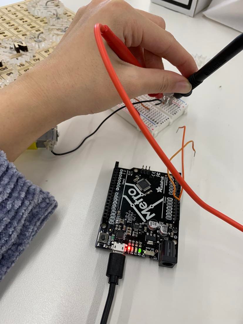
I used a breadboard in order to power my motor. The motor turns a plastic stick and I had designed one of my gears to attach to it through a 6X6 hole. I used a breadboard that includes wires and a potentiometer to make it turn. Here is a picture of it.
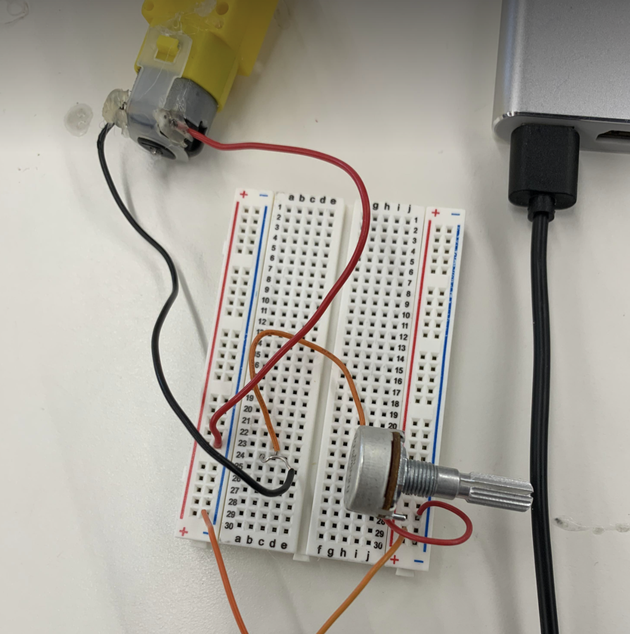
The motor turns quicker as I turn the potentiometer.
Here is a gif of my gear attached to the motor spinning.
Here is a gif of me turning my sculpture with my hand.
Here is the gif of it turning with a motor!
Ultimately, I learned a lot of things including to "document as you go" aka record videos while it still works. Because although I do have a video of it turning with the motor and my hand, it genuinely worked flawlessly before I glued the letters on so I really wish I had recorded that.
Ohm's law
With the potentiometer turned to the setting that it was in the video, I saw that it was 150 Ohms of resistance. Since volage (which I had set to 5V on the arduino) = current*resistance, I got a current of 1/30 volts/ohms. Since ohms =volts/amps, this means I got a current of 1/30 amps. Here's a picture of me showing how I measured the resistance